Cool the electronics inside a machine by tracing the path from its air inlet to the part that runs hot. A CNC controller, servo drive or compact power supply can need a different fan even when the equipment is installed on the same line.
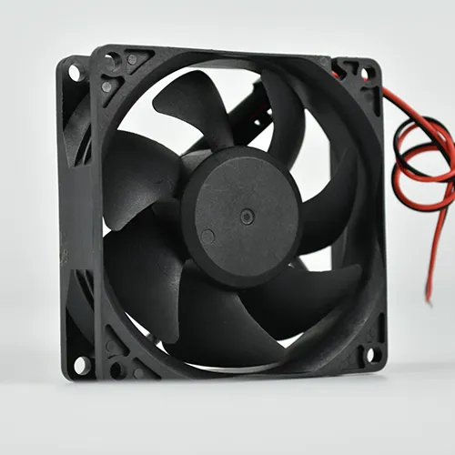
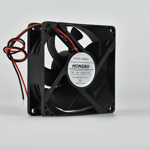
Hongbo 8025 DC axial fan, a compact frame candidate for local equipment cooling.
Locate the heat source inside the machine
Servo and spindle drive compartments
Record which drives dissipate heat during a representative machine cycle. Follow the air past drive heat sinks and cable bundles. Use the operating point behind the installed grille and baffles when choosing a fan.
CNC controllers and machine electronics
For localized airflow, check the fan mounting envelope and the path past the heat sink or board. Identify the available electrical supply, fan monitoring signal and clearance at the connector. Use the actual service cover in the sample check.
Separate control cabinets
When the fan serves the whole electrical enclosure, start with total heat loss, temperature rise and the inlet and outlet filter arrangement. See control cabinet cooling.
Shortlist by fit and electrical interface
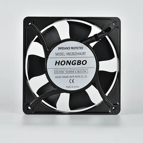
A 120 mm AC frame
The 12025 AC is one candidate for an AC electronics compartment with a 120 mm opening. The catalogue describes a 25 mm nominal family while its side drawing shows 26 ± 0.5 mm. Use the current drawing and retain space for wiring and the cover.
A compact DC frame
The 8025 DC is an 80 × 80 × 25 mm model. Match the exact supply and termination to the controller. If the equipment needs speed control, feedback or an alarm, confirm the required signal and the available version with the model data.
Use the intended mounting and service covers, the same inlet condition and a representative machine workload. Record the highest relevant component temperature and the periods of peak load.
Protect the air path
Keep dust, coolant and oil mist exposure in the equipment specification. If ventilating the compartment admits contaminants, evaluate filtered or isolated cooling. Confirm any protection claim for the complete selected assembly.
Make the check repeatable
Retain the fan suffix, electrical interface, drawing revision, control setting and measurement locations. If cable routing changes or a filter is added, repeat the affected fit and airflow checks.
Share the heat source, installation envelope, power supply, operating temperature and target airflow at pressure if known. Add the current part label or a marked drawing for a replacement.