Home / Engineering Resources / Application Examples
Sizing an 80 mm fan for an electronics bay
A compact 24 V electronics bay has an 80 mm fan position and needs a speed signal for monitoring. This worked example follows a Hongbo 8025 candidate from a heat estimate through the evidence needed to approve a fitted sample.
Screening duty in this example
30 CFM at 25 Pa
- Supply
- 24 V DC
- Nominal fan space
- 80 × 80 × 25 mm
- Monitoring
- Speed feedback required
Start with the heat and the air path
The heat load sets the first airflow estimate
Suppose 200 W of heat must leave with the air and the allowed bulk air temperature rise is 12°C. With air density about 1.20 kg/m³ and specific heat about 1,005 J/(kg·K), the steady heat balance gives the following estimate.
200 W ÷ (1.20 × 1,005 × 12) ≈ 0.0138 m³/s
29.3 CFM rounded to 30 CFM for screening
A tighter 8°C rise would raise the estimate to about 43.9 CFM at the same heat load. Confirm the actual heat entering the airflow and the ambient condition before setting the final target.
The enclosure determines pressure
The example assumes 25 Pa of resistance at 30 CFM. Measure or estimate the installed path with the cover, grille and obstructions in their intended positions.
- Inlet grille
- Electronics bay
- 80 mm fan
- Outlet
The fitted fan operates where its pressure–airflow curve meets that resistance. Ask for the curve for the exact 24 V configuration and check it at the required duty point.

Put the 8025 family on the shortlist
The 8025 listing gives the nominal 80 × 80 × 25 mm body, 12 / 24 / 48 V choices and up to 54 CFM at high speed. The family fits the initial size and supply screen. Continue the review with the full suffix for the 24 V version.
- Geometry. Request the drawing for the full suffix. Check hole centres, fasteners, lead exit and the actual space behind the grille.
- Electrical interface. Ask for the 24 V rating, current, connector and feedback pin assignment. The family listing describes power leads. Confirm the available speed feedback and that the equipment can read it.
- Air performance. Read the airflow at 25 Pa on the curve for the exact voltage and speed configuration. Use that value to see whether this variant reaches the 30 CFM target under load.
Advance to a fitted sample once the exact variant has the required geometry, feedback and airflow at the duty point. If the curve falls below the target there, review the inlet and outlet losses or screen a different candidate before sampling.
Approve the installed result
Record the full part number and the actual fan supply and setting. With the cover fitted, verify airflow and pressure together, then review the electrical and thermal checks at the agreed load.
- Airflow at pressure
- Record the measured pair with grille and cover fitted. Compare with the 30 CFM at 25 Pa screening target or your revised requirement.
- Temperature
- Note the ambient and load, bulk air rise and the hottest relevant component readings. Use the agreed limits for the equipment.
- Fit and monitoring
- Confirm the fitted depth, start behaviour and feedback under the intended supply. Record the connector and drawing revisions from the accepted sample.
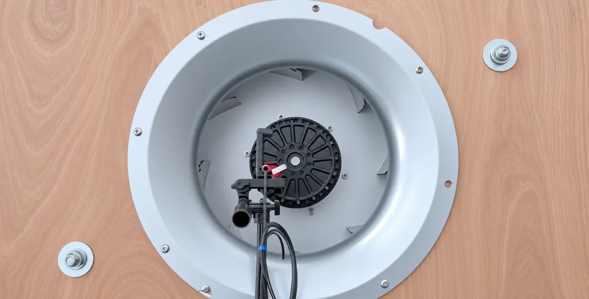
Send the airflow and pressure as a pair
Share your mounting envelope, actual supply, desired feedback output and target airflow at pressure. Include the heat load, grille or filter and intended sample check when known.
Other equipment changes the decision
Filtered control cabinet · about 40 CFM
A separate worked example uses a 120 mm position and actual 50 Hz Hongbo catalogue curves under an assumed filter and enclosure resistance. The 12025 AC stays on hold under those conditions, and the 12038-7P merits verification. Check fitted depth and the exact electrical version before sampling.
Refrigeration coil · 150 m³/h at 55 Pa
For this example duty, the 180-49 AC centrifugal blower is a family to screen. Supply the outlet direction, flange and service clearance with the duty point. Compare the proposed suffix and speed curve to the coil and shroud condition, then test the fitted assembly.