Specify a fan for a DC fast charger’s power module, electrical bay or ventilated enclosure. Hongbo Motor can review an existing fan or a new air path against the available space, supply and duty.
Illustrative air paths. Use the actual module and enclosure drawings to verify the installation.
Separate module cooling from cabinet ventilation
A module fan moves air through a defined heat-sink passage. An enclosure fan serves the cabinet air exchange and must be selected against the cabinet’s own inlet and outlet arrangement.
Power-module drawer
Start with the manufacturer’s module loss and permitted component temperatures at sustained charging duty. Use the inlet area, fin geometry and exhaust shape to determine pressure. Check whether adjacent drawers can recirculate their exhaust.
Mechanical. Depth, hole centres and cable exit with the module fully seated.
Electrical. Actual auxiliary supply, startup current and the control/feedback interface.
Acceptance. Record temperatures and fan setting at the required module load.
Enclosure and auxiliary bay
Select on the closed enclosure’s air path with the intended filter, weather cover and exhaust fitted. Check how outdoor ambient, installation clearances and filter loading affect airflow, and retain room for filter service.
Mechanical. Grille, filter and panel geometry with the cabinet closed.
Electrical. Available supply and speed limits at idle and sustained charging.
Acceptance. Record cabinet temperatures, ambient and filter condition with the sample.
Hongbo 12038 EC product gallery. Use the approved variant drawing for the connector and mounting interface.
When the module already has a 120 mm fan position
Compare the actual 120 × 120 × 38 mm envelope before choosing the electrical version. A mechanically similar frame can use a different supply, interface and airflow curve.
12038 DC
The catalogue lists 12 V, 24 V and 48 V DC options. Use the available charger rail to request the corresponding speed variant, input current and curve.
The listing identifies 0–10 V and PWM options for the family. Confirm the power input, exact control interface and operating curve with the complete quote suffix.
A 60 × 60 × 25 mm listed frame is an option to review for a small controls bay with limited volume. Compare the bay’s restriction, connector access and required duty before choosing a grade.
Use the intended power module and door configuration, then reproduce representative charge and standby conditions. Retain the actual supply and speed setting with every measurement.
Sustained charge. Run to the project’s steady condition at representative load and design ambient. Record the temperatures of the monitored components and the fan operating condition.
Standby and restart. Confirm the requested idle behavior and check startup at the project’s lowest approved speed or control setting. Match the feedback and alarm behavior to the drawing.
Installed service. Check intake and exhaust clearance, access to filters and the effect of the selected media condition. Keep the fan, harness and drawing revisions together.
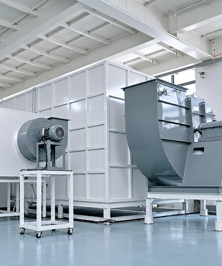
Hongbo airflow test equipment. Charger acceptance uses the actual installed configuration.
Send a drawing, the source of the heat loss and the required airflow at pressure. Include available supply, fan clearance, controls and sample timing so the response can identify the specific variant and files.