Fan Guard & Filter Fit Guide
Match the guard, filter and fan to the cabinet panel. Compare three Hongbo accessories, read the reference drawings and check the fitted assembly before you approve a part.
Choose the accessory by what it needs to do
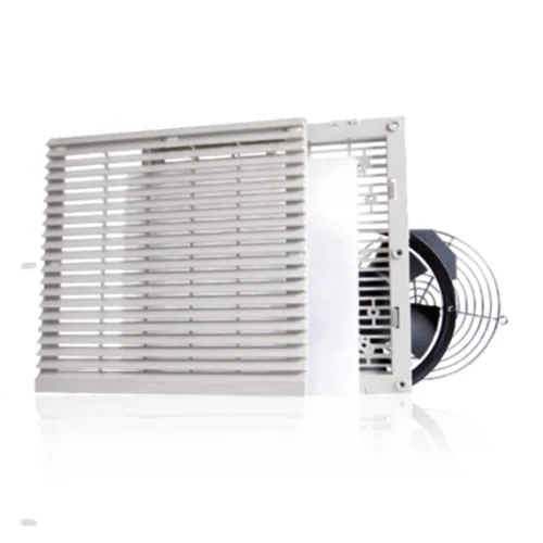
A wire guard limits access to the impeller. A louvered filter holds media in the air path. If the cabinet needs both functions, review the actual combination on the assembly drawing.
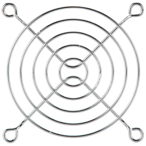
JL-120
120 mm fan class · Steel wire guard
Start here when an accessible opening needs a blade-contact barrier. Verify the mounting span, the screw arrangement and the gap to the impeller on the side you plan to guard.
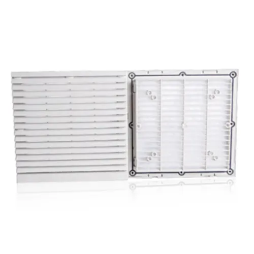
HB-804
120 mm fan class · Louvered filter
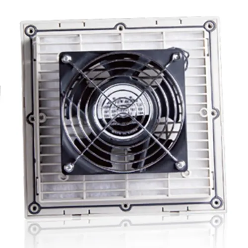
Shortlist this assembly for a filtered intake in the 120 mm fan class. Check the chosen mounting style and the space needed to remove the cover and media.
HB-805
172 mm fan class · Louvered filter
Start here for a larger filtered opening. Send the actual fan frame and panel drawing, especially when comparing a 172 × 150 mm frame with a square 172 mm frame.
Check the panel before you cut metal
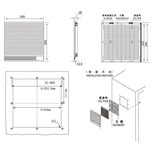
A fan class, a cover size and a panel opening refer to different dimensions. Put the fan, accessory and cabinet drawings together and review the mounting side and reference faces.
One opening, four checks
- Opening and hole pattern. Record the opening shape, corner clearances and hole centres on both axes. Compare with the actual fan and accessory drawings before drilling.
- Panel and fastening. Confirm sheet thickness, clip range or screw engagement. Account for any gasket or stand-off and orient the guard or grille on the intended side.
- Depth and clearances. Check the fan, accessory and fasteners as a stack. Leave clearance for the impeller, cable bend and neighbouring equipment when the door closes.
- Service access. Check that the cover can open or come off and that the media clears adjacent doors, trays and wiring along its removal path.
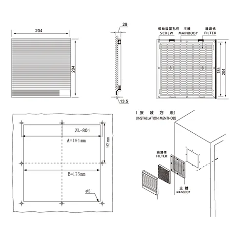
120 mm fan class, 204 mm cover on the reference
The HB-804 listing calls out a 120 mm fan class. Its ZL-804 reference shows a 204 mm cover view. The HB-805 listing calls out a 172 mm fan class and shows a ZL-805 reference with a 255 mm cover view. For either assembly, confirm the applicable drawing revision and use its panel view for the opening and drilling pattern.
Check the guard span on the correct view
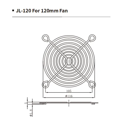
The JL-120 front view shows a 105 mm horizontal span between the mounting loops. Compare both axes and the side view with your exact frame and fasteners. The guard must stay clear of the impeller after tightening.
Verify airflow through the assembled cabinet
Check the fan curve for the exact variant and supply or speed setting. Evaluate it against the resistance of the actual air path and confirm the working point on the fitted sample.
- InletLouver and filter media
- FanInstalled orientation and speed
- CabinetEquipment and internal restrictions
- OutletGrille or exhaust filter
Illustrative intake layout. Confirm flow direction and the actual position of each part on your cabinet drawing.
Agree on the working point
Use the required airflow and pressure together. Include the intake, media, cabinet and outlet. If you have measured pressure loss for the complete assembly, use that result directly. For components in series, compare their losses at the same airflow. Ask for the pressure-drop data for the selected filter media when it is needed for the calculation.
Check the filter as it loads
Record a clean-media baseline with the door closed and both air openings fitted. Agree how the unit will be judged at the service limit for that media, using an airflow, pressure or thermal criterion appropriate to the equipment. Confirm that air passes through the intended path and that media can be replaced without disturbing the fan.
Approve the assembly before you order
Take the selected part through a dry fit, an installed run and a service check. Tie the results to the same fan suffix, accessory and drawing revision that will appear on the order.
- Dry fit. Check opening alignment, full fastening engagement, blade clearance and door closure. Save a photo of the panel and mounting side.
- Installed run. Check air direction and confirm the agreed airflow or cabinet temperature criterion with all parts installed. Record supply or speed, filter condition and how the result was measured.
- Service check. With the equipment safely isolated, remove and refit the specified media. Confirm access, seating and how replacement media will be identified for spares.
Send the panel drawing and part numbers
Attach your panel drawing or a marked-up photo to the email draft. Include the full fan suffix, accessory model, mounting side and airflow requirement. Ask for the applicable mounting revision, media specification or pressure-drop data for that combination.