Fan Failure Monitoring and Redundant Cooling
Decide whether your equipment must keep running, reduce its load or stop safely when a fan is unavailable. Check the response with the covers and filters in place at the specified load.
Read the signal at the right level
- Fan feedback
- A tachometer reports rotation. A dedicated alarm output reports the state defined in that fan’s drawing.
- Equipment response
- The controller identifies the fault and selects the required operating state.
- Cooling performance
- Airflow or temperature measurements confirm how the equipment behaves in that state.
Specify the feedback for your 12038 DC variant
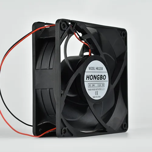
Hongbo lists a 120 × 120 × 38 mm DC axial fan family in 12, 24 and 48 VDC configurations. PWM and tachometer options depend on the selected model. Identify the suffix and confirm the combination you need on its drawing.
Give the controller team the expected signal in normal operation, at startup and when feedback is absent. Confirm whether it should read speed pulses or an alarm state. Agree how the controller will distinguish a stopped fan from a missing signal where the distinction affects its response.
Test the equipment after the loss of one fan
Agree on the permitted load, environmental conditions, fault timing and thermal or airflow limit before the test. Repeat the test for each fan position that can create a different air path.
| Equipment state | Record during the test | Evidence for release |
|---|---|---|
| Normal operation | Fit all trays, covers and filters. Record each fan’s command and feedback, the equipment load, inlet temperature and airflow or the agreed temperature points. | The normal readings at the approved load define the baseline. |
| One fan unavailable | Use the equipment’s approved test method. Log the affected fan, time to alarm, action on the remaining fan or controller, and the air or temperature reading at the agreed location. | The equipment reports the correct fault and meets the cooling limit for as long as it will remain in the specified state. |
| Return to service | Restore the approved configuration and observe the restart, alarm reset and return to the expected load and cooling. | The system returns to the approved state and the event record shows which unit was affected. |
If the equipment permits an empty tray slot during service, include the approved blanking or isolation arrangement in that test. An open slot can change airflow through the remaining bays. Check the direction and spacing of any approved spare.
Keep the failure test with the approved assembly
- Scope of the test
- Describe which condition was tested. A lost tachometer signal, a fan without power and an empty bay can have different effects. Record which fans share a supply or controller and whether your test covers that shared component.
- Arrangement that passed
- Keep the fan suffixes, the mounting and airflow direction, the wiring revision and controller settings. Record the alarm time, the operating load and the measured result for each position.
- What to recheck after a change
- Review the affected tests if the fan, controller logic, filter resistance or tray layout changes. A service spare needs the approved air direction and the interface used in the test.
Send the fan label and the required alarm response
Include supply voltage, the available space, how many fans share the air path and the cooling your equipment needs during a fault. Hongbo can use the complete suffix to identify the applicable connection drawing.