
Fan Noise and Vibration Validation
Use the catalogue to select candidates. Agree on sound and vibration limits, measuring points and operating conditions before testing the installed fan.
Identify which result your project needs
- Catalogue acoustic value
- Sound pressure is measured at a point. Sound power describes total sound emitted by the source under the test conditions. Identify the reported quantity before comparing data. For sound pressure, request the microphone position, mounting, airflow and background conditions.
- Installed sound and vibration
- Specify the loaded assembly, fan control mode and measuring positions. Use that same setup each time you compare a sample or revised configuration.
- Balance evidence
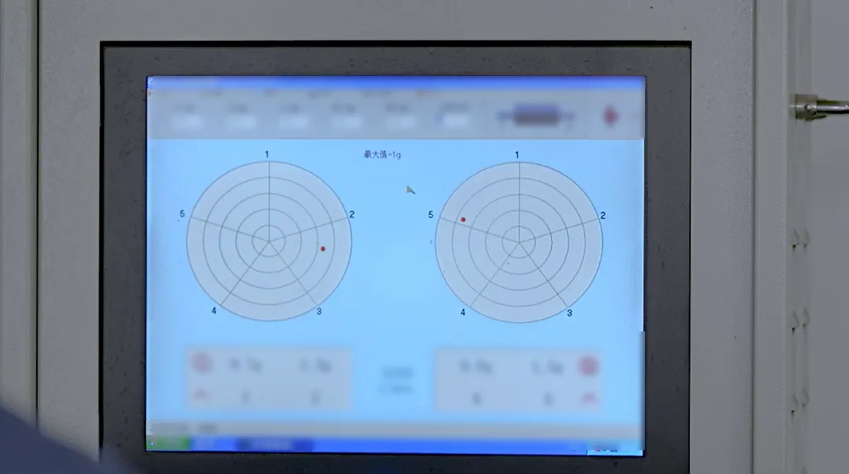
- For a rotating assembly, ask what was checked and under which speed and fixture conditions. Keep the balance record with its part revision. Measure installed vibration at the relevant fan or enclosure location for the equipment decision.
Compare catalogue entries at the right frequency
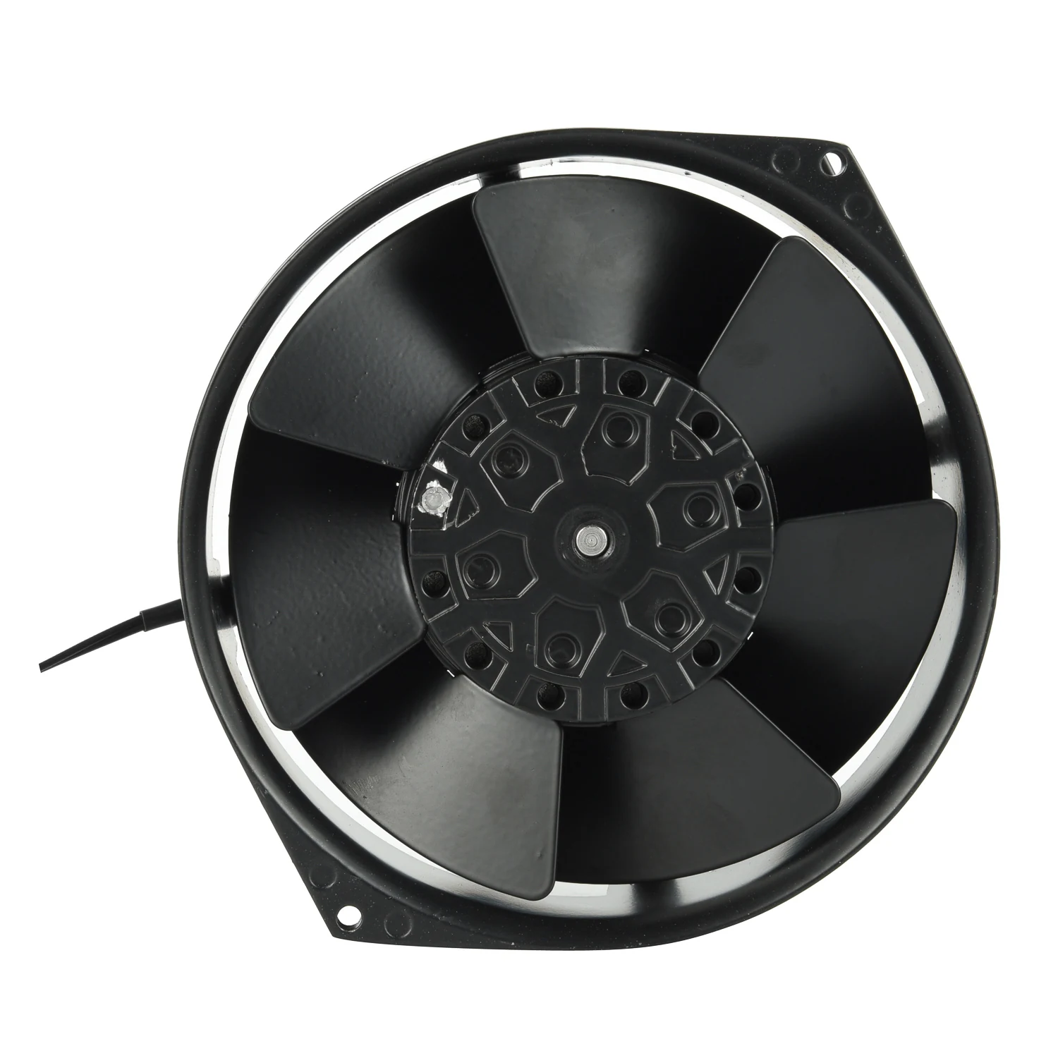
The 17055 page lists HB17055HA2B-7P as a ball-bearing variant for 200/240 V AC. This one row shows how speed, listed noise and airflow change between 50 and 60 Hz.
| Supply frequency | Speed, rpm | Listed noise, dB(A) | Airflow, CFM |
|---|---|---|---|
| 50 Hz | 2,800 | 48 | 191 |
| 60 Hz | 3,100 | 52 | 224 |
Use the 60 Hz entries for a 60 Hz shortlist. Request the test basis behind the listed noise value and the frequency-specific curve at the required static pressure. Assess the actual equipment at the airflow and mounting it will use.
Write an acceptance check someone can repeat
- Match the assembly and duty
- Record the full model, supply and frequency or control setting, measured speed, airflow and pressure. Identify the installed panels, grille, filter and mount. Specify which modes must pass, including any start-up or high-load condition that matters.
- Set the acoustic measurement
- Name the acoustic quantity, weighting, measurement points and distance. Agree which side of the equipment faces the microphone, what background conditions apply and how the result is reported for each mode.
- Set the vibration measurement
- State the direction and location of the sensor, the quantity and units to report, and the applicable limit. Keep the fan-frame measurement and the value on the host panel identified separately.
- Record the decision
- Agree who takes the measurements and who accepts them, which limits apply at each point and where the record is kept. Capture the test date, sample identity, fixture and revision.
Carry the installed result with the sample
If a pilot unit changes its grille or filter after the first test, check the airflow and speed in the revised assembly. Repeat the agreed sound and vibration measurements with the panels in their approved positions.
- Keep the published row and requested test basis with the sample identification.
- Record sound and vibration against their own limits in the assembled equipment.
- Carry the accepted conditions and revisions into the installation and approval record.
Send the measurement conditions and the limit
Share the full model, equipment layout, operating mode and the measurement you need. Include the proposed acceptance limit and identify any change since the last approved sample.